1

I have been testing for weeks a circuit with a STM32G030F6P6TR, which has no high speed clock, as it is a TSSOP20 encapsulation.

Only an LSE or clock bypass can be configured. I have tried with STM32Cube to configure the micro (I'm a newbie, I come from arduino) but I can't get the microcontroller to work.

Example images of when it works enter image description here
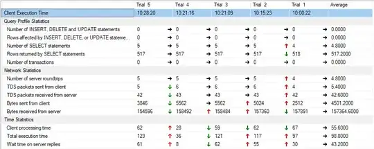
enter image description here

If I set the clock as HSI RC, the program works and if I do a bypass and inject a 8 Mhz signal from a frequency generator, it also works correctly. But if I set the crystal to 32.768 Khz and configure in the "System Clock Mux" as LSI RC or LSE, the code does not work.

Sample images of when it does not work enter image description here
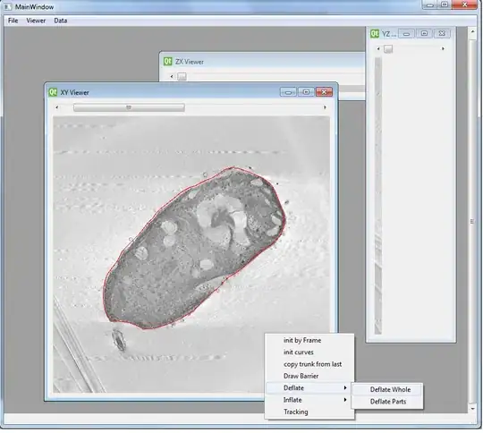
enter image description here

Can't it work with a low frequency crystal, do I have to configure something else that I left out?

I want to learn how to correctly choose a micro in case I have chosen the wrong one.

Thank you very much.

Regards.

Anto
  • 313
  • 1
  • 3
  • 13
  • This part can do LSE or HSE but not both. You have to configure in the syscfg block which pin you want to map. Once you have done that you can enable the respective clock and set it as system clock source. – Tom V May 18 '23 at 17:03
  • If you select LSI RC or LSE as the system clock source, the device will be extremely slow. It just appear to not work. Strangely enough, in STM32CubeMX/IDE, both "BYPASS Clock Source" and "OSC enable" must be checked to configure the device for HSE. – Codo May 18 '23 at 17:45
  • @TomV The images were an example of the way it worked for me. Next I put other images of the form that does not work for me, maybe I am configuring something wrongly. – Anto May 19 '23 at 11:56
  • @Codo The problem is that it doesn't work fast or slow, it doesn't work. I have a code that only activates the outputs to turn on some example LEDs and these do not blink, only when I configure HSI or Bypass. – Anto May 19 '23 at 11:58
  • Two things could possibly go wrong: (1) Crystal isn't oscillating properly. Enable "Master Clock Output" and select "LSE" on the MCO Source Mux. Then you can measure the frequency on pin PB0. (2) Systick interrupt triggers 1000 times a second. At a system clock of 32kHz, it likely uses up all CPU power (32 ticks per interrupt is probably not sufficient). Lower the systick frequency to 10Hz. – Codo May 19 '23 at 12:39
  • @Codo Before writing the question, I tried to measure with the oscilloscope the clock signal and I could check that the crystal is not oscillating. Now, with your indications, I have configured MC0 (LSI) and System Clock Mux (LSI) and I can see that there is no output. Neither with LSE. – Anto May 19 '23 at 16:52
  • Use a debugger to see how far you code gets and what's actually happening. My guess is it is so slow it's stuck in interrupt handlers and even unable to complete the clock configuration. – Codo May 19 '23 at 18:00
  • @Codo I will try to see it, I am very new to stm32cube, I come from smt32duino. – Anto May 31 '23 at 08:34
  • @Codo How can I test if it works correctly? I have opened the debug but I don't really understand what to look for. – Anto Jun 02 '23 at 16:44
  • Stop the program and check where in the code it stopped. Then continue and stop the program several more programs. If it stops in the systick handler several times, then the systick handler requires more CPU time than is available. If it is stuck in the clock configuration, then there might be a problem there. If it is stuck in a fault handler, there is another problem. And so on... – Codo Jun 03 '23 at 07:02

0 Answers0