1

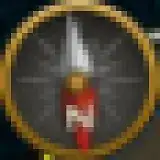
I am building a video game overlay that sends data back to the player to create a custom HUD, just for fun. I am trying to read an image of a video game compass and determine the exact orientation of the compass to be a part of my HUD.

Example photo which shows the compass at the top of the screen:

(The circle currently facing ~170°, NOTE: The position of the compass is also fixed)

Example photo which shows the compass at the top of the screen:

Example photo which shows the compass at the top of the screen

Obviously, when I image process on the compass I will only be looking at the compass and not the whole screen.

This has been more challenging for me compared to previous computer vision aspects of my HUD. I have been trying to process the image using cv2 and from there use some object detection to find the "needle" of the compass.

I am struggling to get a triangle shape detection on either needle that will help me know my orientation.

The solution could be lower-tech and hackier, perhaps just searching for the pixel on the edge of the compass and determining that is the end of the needle.

One solution I do not think is viable is using object detection to find a picture of a compass facing true north and then calculating the rotation of the current compass. This is due to the fact that the background of the compass does not rotate only the needle does.

So far I have applied Hough Circle Transform as seen here: https://opencv24-python-tutorials.readthedocs.io/en/latest/py_tutorials/py_imgproc/py_houghcircles/py_houghcircles.html#hough-circles Which has helped me get a circle around my compass as well as the middle of my compass. However, I cannot find a good solution for finding the facing of the needle compared to the middle of the compass.

circle detection

I understand this is a pretty open-ended question but I am looking for any theoretical solutions that would help me implement a solution. Anything would help as this is a strange problem for me and I am struggling to think how to go about solving it.

Christoph Rackwitz
  • 11,317
  • 4
  • 27
  • 36
  • 1
    Is the location of the compass fixed? – Jeru Luke Sep 09 '22 at 15:09
  • Yes, it is. It will be in the exact same spot on the screen. – programmer4g Sep 09 '22 at 15:11
  • If so, you can crop the region containing the compass and focus on that region alone. – Jeru Luke Sep 09 '22 at 15:26
  • I wouldn't be looking for circles or triangles. If the position of the compass is fixed, you can mask and just look at pixels just inside the gold perimeter (for best location accuracy). Do a HSL transform and look for reds just inside the gold ring. – Mark Setchell Sep 09 '22 at 16:40
  • do you mean **that tiny thing there?** https://i.stack.imgur.com/E1sZi.png I hope not, that's gonna be murder to work with -- you definitely should *not* try to _find_ it, but _know_ where it is, and blindly take that region for processing. then perhaps try a polar warp to make the problem 1D linear... or get views of this thing in a dozen or two orientations and make a "filter bank" from it, see which filter matches best. don't use CCORR matching modes, use SQDIFF modes (sum of squared differences, do not multiply/"correlate") – Christoph Rackwitz Sep 09 '22 at 16:41

3 Answers3

2

In general I would suggest to look at a thin ring just beneath the border or your compass (This will give you lowest error). Either you could work on an image which is a polar transform of this ring or directly on that ring, looking for the center of gravity of the color red. This center of gravity with respect to the center of your compass should give you the angle. Most likely you don't even need the polar transform.

im = cv.imread("RPc9Q.png")
(x,y,w,h) = (406, 14, 29, 29)
warped = cv.warpPolar(
    src=im,
    dsize=(512, 512),
    center=(x + (w-1)/2, y + (h-1)/2),
    maxRadius=(w-1)/2,
    flags=cv.WARP_POLAR_LINEAR | cv.INTER_LINEAR
)

warped

Christoph Rackwitz
  • 11,317
  • 4
  • 27
  • 36
Flow
  • 551
  • 1
  • 3
  • 9
2

Here's some more elaboration on the polar warp approach.

  • polar warp
  • take a column of pixels, being a circle in the source picture
  • plot to see what's there
  • argmax to find the red bits of the arrow
im = cv.imread("RPc9Q.png") * np.float32(1/255)
(x,y,w,h) = (406, 14, 29, 29)

a closer look

# polar warp...
steps_angle = 360 * 2
steps_radius = 512
warped = cv.warpPolar(
    src=im,
    dsize=(steps_radius, steps_angle),
    center=(x + (w-1)/2, y + (h-1)/2),
    maxRadius=(w-1)/2,
    flags=cv.WARP_POLAR_LINEAR | cv.INTER_LANCZOS4
)
# goes 360 degrees, starting from 90 degrees (east) clockwise
# sample at 85% of "full radius", picked manually
col = int(0.85 * steps_radius)

# for illustration
imshow(cv.rotate(cv.line(warped.copy(), (col, 0), (col, warped.shape[0]), (0, 0, 255), 1), rotateCode=cv.ROTATE_90_COUNTERCLOCKWISE))

enter image description here

signal = warped[:,col,2] # red channel, that column
# polar warp coordinate system:
# first row of pixels is sampled at exactly 90 degrees (east)
samplepoints = np.arange(steps_angle) / steps_angle * 360 + 90

imax = np.argmax(signal) # peak

def vertex_parabola(y1, y2, y3):
    return 0.5 * (y1 - y3) / (y3 - 2*y2 + y1)

# print("samples around maximum:", signal[imax-1:imax+2] * 255)
imax += vertex_parabola(*signal[imax-1:imax+2].astype(np.float32))
# that slice will blow up in your face if the index gets close to the edges
# either use np.roll() or drop the correction entirely

angle = imax / steps_angle * 360 + 90 # ~= samplepoints[imax]

print("angle:", angle) # 176.2
plt.figure(figsize=(16,4))
plt.xlim(90, 360+90)
plt.xticks(np.arange(90, 360+90, 45))
plt.plot(
    samplepoints, signal, 'k-',
    samplepoints, signal, 'k.')
plt.axvline(x=angle, color='r', linestyle='-')
plt.show()

plot

Christoph Rackwitz
  • 11,317
  • 4
  • 27
  • 36
1

I have been able to solve my question with the feedback provided.

  1. First I grab the image of the compass: step_1

  2. After I process the image crop out the middle and edges of the compass as seen here: step_2

  3. Now I have a cropped compass with only a little bit of red showing where the compass needle points. I masked out the red part of the image. step_3

  4. From there it is a simple operation to find the center of the blob which roughly outputs where the needle is pointing. Although this is not perfectly accurate I believe it will work for my purposes. step_4

  5. Now that I know where the needle end is it should be easy to calculate the direction based on that.

Some references: Finding red color in image using Python & OpenCV https://www.geeksforgeeks.org/python-opencv-find-center-of-contour/