I am starting on my E-ink project, but I got stuck. This is the connection diagram I made based on the three components. An SD card module, an E-ink screen module (screen not visible now), and the Arduino uno.
modules and connections :
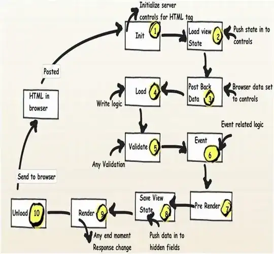
I know that both modules work when I connect them separately to the Arduino in this way, but when I want to connect both, 3 wires overlap as you can see (red cirkels). I understand that you have to put the CS (or SS, source select, different name, same thing) of both modules on a separate pin. How do I do this best? I only see one SS (or CS) port on the Arduino uno, see attachment. Can I set another port as SS or is that not possible? I also have two other cables on the same port. I understood from the internet that: sdi = mosi and sck = miso so I can connect them to the same port. It is especially important that you make it clear which slave you want to use at what time. The data lines are used for both modules, they don't need separate data lines, see SPI diagram image.
I also have a programming question that goes along with the first question. The program I want to make is as follows in psuedo code:
-Power on-

Setup;
Turn off sd card,
Turn off e-ink screen,
.bmp counter = 0;

Loop;
{
Turn on sd card,
Open sd card and read .bmpcounter value (which image the uC should read),
Load that .bmp file into ram memory,
Turn on e-ink screen,
Draw .bmp file on the screen,
Turn off e-ink screen,
Turn off sd card,
SD card .bmp counter +1 (go to next image),
Count up to 24 hours in low power mode,
Get out of low power mode,
}
How can I translate this to Arduino IDE or c++?
If this really isn't possible with this Arduino (I assume it is, because others have also managed to do it with more complicated ideas with e-ink), I also have other uCs, such as the raspberry pi pico, but I would prefer use it because of the available documentation and arduino IDE programming environment.
I would very much like to hear from you how I can approach this. Thank you for your time,
-Casper Tak