0

This is a programming question which has hardware limitations. I am working on a reverse engineering / hacking project of a "smart" thermostat. (which was not so smart, but it will be able to handle MQTT traffic.)

My problem is with the built in LED matrix display. There are 5 seven segments, two of those have DP as well and 19 icons all around the display.

Normally I would resolve the display like this:

 #define MAKE_BINARY(a,b,c,d,e,f,g,h) (((a)<<7)|(b)<<6)|((c)<<5)|((d)<<4)|((e)<<3|((f)<<2)|((g<<1)|h))
    
    
 static unsigned char int_to_7leds [] = {
  MAKE_BINARY (0,0,0,0,0,0,1,1), // 0
  MAKE_BINARY (1,0,0,1,1,1,1,1), // 1
  MAKE_BINARY (0,0,1,0,0,1,0,1), // 2
  MAKE_BINARY (0,0,0,0,1,1,0,1), // 3
  MAKE_BINARY (1,0,0,1,1,0,0,1), // 4
  MAKE_BINARY (0,1,0,0,1,0,0,1), // 5
  MAKE_BINARY (0,1,0,0,0,0,0,1), // 6
  MAKE_BINARY (0,0,0,1,1,1,1,1), // 7
  MAKE_BINARY (0,0,0,0,0,0,0,1), // 8
  MAKE_BINARY (0,0,0,0,1,0,0,1), // 9

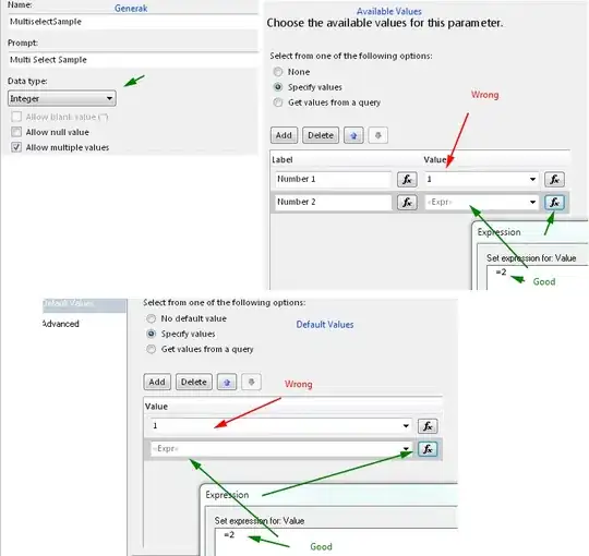
However, there is a slight problem with this. there are five 74HC595 shift registers on the board, which are tied to the LEDs like this: enter image description here
This is not something you would normally want to do when designing stuff, at least I try to keep it like 8 bits (1 SR) / 7 segment and at the end take care of the rest.

As I have already mentioned this is pure hacking, I do not have the original code or the schematics. I would like to ask for some help on how to manipulate the 7 bytes to break it down to something like:

  • 5 characters
  • 21 boolean variables to set everything else

I have started to think about a 56 bit long variable and a huge switch-case structure to set each of the characters, but there should be some other nicer solution out there.

Thank you for reading this!

All suggestions are welcome.
Zoszko
  • 75
  • 1
  • 7
  • I don't follow all the way, but seems like one should have an interface between the code and the display? – Neil Feb 13 '21 at 23:23
  • Without a little more code it's not very easy to help you, but I'd say that you could have an array for each number to map which registers must be used to create a number and it should be ordered like the 0s and 1s in your `int_to_7leds` variable – Jack Lilhammers Feb 14 '21 at 02:53
  • There are 7 shift registers, which means seven shiftOut()-s, but as you can see the drawing the designer did not really follow any logic. So shift register no. 0 controlls some of the icons and the lower section of the second and third character. If I have to change the second character on the display I have to manupulate both the 0. and the 2. BYTE. I am working on something now, I will post it once I am done with that. – Zoszko Feb 14 '21 at 08:57
  • You can use two levels of abstraction, first building the segment pattern for one digit by the number to show, and second putting the resulting bits in the buffer to shift out. The first part is straight forward, but the second part is tricky. -- Anyway, this question is really broad as several solutions are possible, and seems to seek for recommendations. – the busybee Feb 14 '21 at 17:12
  • @thebusybee The second part was the easiest for me! :) See my answer below. – Zoszko Feb 14 '21 at 20:29

1 Answers1

1

First of all thank you guys and girls for all the comments, I have figured it out in the meantime. So shifting out is just simple bit banging, that why I have posted this here and not into the electronics section.

So I have made the following:

int * resolve_chars(char input, int *ch){

switch (input)
{
case 0:
  // statements
        ch[0] = 1;
        ch[1] = 1;
        ch[2] = 1;
        ch[3] = 1;
        ch[4] = 1;
        ch[5] = 1;
        ch[6] = 0;
  break;
case 1:
.
.
.

This is a very long switch-case function that returns the ch in the end.

I have prepared variables for the icons and arrays for each of the characters (+a helper, because C cannot return arrays as it turned out...)

c1 = resolve_chars( - SINLE CHAR TO BE RESOLVED - , c1h);

This gives me bitmap, for this I simply have to shift out 7 BYTES to update the whole display.

        GPIO_SetBits(GPIOE, GPIO_Pin_3); //OE 
        SetDisplayState(0, MAKE_BINARY (c4_dp,back,hand,no_7,power,settings,no_1,c1[3])); //6
        SetDisplayState(0, MAKE_BINARY (rect,c5[2],c5[1],c5[6],c5[0],c5[3],c5[5],c5[4])); //5
        SetDisplayState(0, MAKE_BINARY (kor,c4[2],c4[1],c4[6],c4[0],c4[3],c4[5],c4[4])); //4
        SetDisplayState(0, MAKE_BINARY (c3_dp,c3[2],c3[1],c3[6],c3[0],lock,c3[5],c3[4])); //3
        SetDisplayState(0, MAKE_BINARY (fan,c2[2],c2[1],c2[6],c2[0],lang,c2[5],c2[4])); //2
        SetDisplayState(0, MAKE_BINARY (ora,c1[2],c1[1],c1[6],c1[0],akku,c1[5],c1[4])); //1  
        SetDisplayState(0, MAKE_BINARY (c3[3],no_7,no_6,no_4,no_3,logo,no_2,c2[3])); //0
        GPIO_ResetBits(GPIOE, GPIO_Pin_3); //OE 

And voilá, its working: enter image description here

Now I can focus on the communicaiton with the onboard ESP8266EX

Zoszko
  • 75
  • 1
  • 7