1

I'm currently learning about shadow mapping from here.

I'm trying to figure why shadow acne is happening at-all, I've tried looking at every video/resource I found online, some relate the issue to floating point rounding errors, other say it's about the size of the shadow map and if it could be infinitely large then this problem wouldn't occur,
but none of the explanation I've seen connects as to why I see this "trippy line pattern": enter image description here

Some explanations even include some sort of abstract drawing that can visually relate to the phenomenon on screen but really don't explain well the underlying reason this happens: enter image description here
I've been scratching my head about this looking everywhere for a whole day for a suffice explanation.
I'm basically looking for a new explanation to this phenomenon, hopefully a clear and friendly one.

Also I would like to know after hopefully understanding the cause of this, how biasing/face culling helps solve this problem, and how they trade this problem for peter penning problem, as I think there's no clear explanation to the why this happens instead of this.

Jorayen
  • 1,737
  • 2
  • 21
  • 52
  • 1
    That diagram seems to explain it pretty well. What do you not understand about it? Also, I'm not sure I'm seeing shadow acne on your picture. It seems more like a broken implementation of shadow mapping. Shadow acne tends to happen at the edges of a shadow. – Nicol Bolas Nov 07 '19 at 22:28
  • @NicolBolas Well going to the resource I've linked you can see they mention shadow acne with pictures showing the problem similar to what i have. If I understand correctly what you're talking about is perspective aliasing, which is not what I'm talking about. And this pictures and the explanation (usually) attached to it in some resource is lacking. They explain it as that the "staircase" is the shadow map projected on the ground which I don't kind understand because the idea of shadow mapping as far as I perceived it is create the shadow map texture in the first pass, and for the second pass – Jorayen Nov 07 '19 at 22:39
  • transform each vertex to light space using the same view projection matrices used for generating the shadow map and then use it to get the depth value in the texture. Not sure how "projecting" the shadow map on the ground fits to this description (atleast in my head). – Jorayen Nov 07 '19 at 22:41
  • 1
    "*transform each vertex to light space using the same view projection matrices used for generating the shadow map*" You just described how projective texturing works. – Nicol Bolas Nov 07 '19 at 22:59
  • I'm sorry as I've said there're some thing I understand and some that I just don't. That's why I'm looking for a "refreshing" explanation of the cause of shadow acne, maybe you could provide one written by yourself and it might help me look at this at a different perspective. – Jorayen Nov 07 '19 at 23:15
  • When I saw that scheme, I have immediately recognised the site. Anyway, from what I understood from it, some pixels sample texels that would indicate that they're below the surface while they actually aren't. This is fixable by applying an offset. – John Nov 08 '19 at 08:04

1 Answers1

4

Shadow Acnee can come from different causes.

The first one is a problem with the precision of your shadow map and the actual depth you compute in your shader. The depth you store in your depth map is mapped from [near, far] to [0, 1].

You go from a linearized floating point value of 32 bits in the [near, far] range to a non linearized depth (more precision the closer you get from 0) in the [0, 1] range stored in maybe 24 bits. To put it an other way some depth value you compute in your fragment shader will be mapped to the same "texture color" wich will cause the depth test to fail.

For example with the given formula

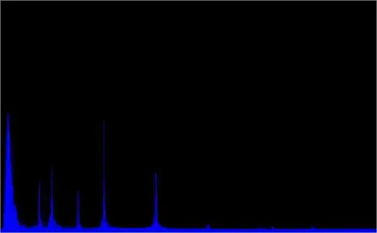
enter image description here

with near = 1 and far = 1000

F(700) = 0.99957, F(701) = 0.99948 ~= 0.9995 

Ence if thoose 2 values are mapped to 0.9995 in the depth map due to precision error. When you will compute the depth test the one of them will fail cause 0.9995 < 0.9957.

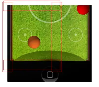
The other problem, can come from a shadowMap being too small for your your actual camera point of view (perspective aliasing).

enter image description here

As you can see in this pictures the side of the tree takes more place in the camera point of view than in the sadowMap. There are more pixels that covers the side of the tree in the screen than in the shadowMap, ence some pixels you compute in the camera point of view will use the same depth information in the lightPoint of view, some tests might point to the same shadow map pixel and will fai. d > ds

Adding a bias in both cases, will remove the floating point error, or will compensate the error when 2 depth test point to the same shadowMap pixel. Adding a bias can be seen as margin of error. With the the bias you accept some tests that were rejected before

Paltoquet
  • 1,184
  • 1
  • 10
  • 18
  • I think that's a good explanation I'm happy with thanks for the examples and the illustrations :) Also would be nice if you could explain how front face culling fixes shadow acne as-well and/or causing peter panning – Jorayen Nov 08 '19 at 09:58
  • For the face culling, It will need a other answer – Paltoquet Nov 08 '19 at 12:30
  • This helped me a lot. I've been looking into different definitions and not getting what "a precision issue" is. Camera pixels and shadow texel comparison with pictures really helped me. Thanks. – Mert Jun 01 '20 at 09:18