1
input

  clk ( clock ) :

        0 1 0 1 0 1 0 1 0 1 0 1 0 1 0 1 0 1 0 1 0 1 ...

required output :

   F   :
        0 0 1 1 0 0 0 0 0 0 1 1 0 0 0 0 0 0 1 1 0 0 ...

How can I get that output over using combinational and sequential circuit (logic gate and flip-flop) ? Can you recommend any topic or web-page ?

3 Answers3

1

do you see the pattern in the output ? it is almost 0 0 1 1 0 0 1 1 0 0 1 1 0 0 .... what does it looks like ?

hint: count the clock, represent the count as a binary number...

now that you can get the above output from your clock, see if you cannot get another bit which you could use to cancel the previous output in order to get the desired output.

hint: look further in the above hint...

Adrien Plisson
  • 22,486
  • 6
  • 42
  • 73
  • do You mean I should use three flip flop ? –  Mar 20 '11 at 11:15
  • i don't know the specific logic implementation... i just told you to count. one clock cycle, you are at `1`, another clock cycle and you are at `2`, another cock cycle, `3`, ... – Adrien Plisson Mar 20 '11 at 11:19
1

Well, the sequence repeats after every 8 bit: 0 0 1 1 0 0 0 0. Now log_2(8)=3, this means you need 3 element counter with output function:

0 0 0 = 0
0 0 1 = 0
0 1 0 = 1
0 1 1 = 1
1 0 0 = 0
1 0 1 = 0
1 1 0 = 0
1 1 1 = 0

Now I personally use :

fun = BooleanMinimize[
  BooleanFunction[{{0, 0, 0} -> 0, {0, 0, 1} -> 0, {0, 1, 0} -> 
      1, {0, 1, 1} -> 1, {1, 0, 0} -> 0, {1, 0, 1} -> 0, {1, 1, 0} -> 
      0, {1, 1, 1} -> 0}][c, b, a]]

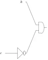
with an output of: b && ! c, but you could use Karnaugh map.

Now you can search wolframalpha.com for: logic circuit b && ! c.

enter image description here

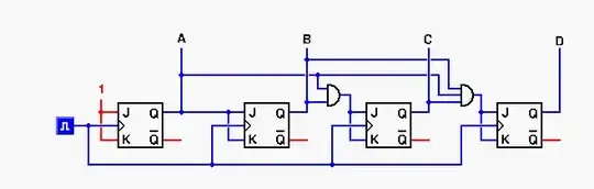
So now you need to make 3 JK-triggers to make 3 element counter, with outputs {a, b, c} and you only need b and c output. You can look up your lecture notes to see how to connect them up.

Simple 4 bit 2 way counter using JK-triggers and some binary logic. enter image description here

  • Upper and operator path is used when counting up.
  • When counting down path below is used.
  • or elements are used to combine them.
  • Extra logic input and inverse is used to determine what way to count.
Margus
  • 19,694
  • 14
  • 55
  • 103
0

The circuits on this page should help, http://www.play-hookey.com/digital/synchronous_counter.html

The 'A' state is the same as your clock:

enter image description here

amelvin
  • 8,919
  • 4
  • 38
  • 59