3

I know that original_image * filter = blur_image, where * is the convolution. Thus, filter = ifft(fft(blur)/fft(original))

I have an original image, the known filter, and the known blurred image. I tried the following code. I just want to compare the computed filter using fft and ifft and compare it with the known filter. I tried in Matlab:

orig = imread("orig.png")
blur = imread("blur.png")
fftorig = fft(orig)
fftblur = fft(blur)
div = fftblur/fftorig
conv = ifft(div)

The result doesn't make sense. I see that div contains many NaN values, and fftblur and fftorig both contain many values of 0. Do I need to do something to this? such as use fftshift?

EDIT: To make this easier to understand, I'm now using the images from: http://matlabgeeks.com/tips-tutorials/how-to-blur-an-image-with-a-fourier-transform-in-matlab-part-i/

I decided to compute the kernel of the origimage and blurimageunpad from that link using:

kernelc = real(ifft2(fft2(origimage)./fft2(blurimageunpad));
imagesc(kernelc)
colormap gray

Here's the result:

https://i.stack.imgur.com/kJavg.jpg

Which clearly doesn't match the gaussian blur mentioned at towards the top of that link

user5739619
  • 1,748
  • 5
  • 26
  • 40
  • The code you post here uses `/` where you want to use `./`. However, that should not prevent the NaN values from appearing where the two operands are 0. – Cris Luengo Feb 16 '18 at 07:30
  • Dividing in the frequency domain is a trick that's rarely useful after it's taught in your signals/systems class, and you've seen one reason why: numerical instability. (You're also conflating linear vs. circular convolution here by failing to zero-pad the FFTs.) You know it's a complicated topic when Matlab Image Processing Toolbox has a large set of [deblurring](https://www.mathworks.com/help/images/image-restoration-deblurring.html) functions. – Ahmed Fasih Feb 17 '18 at 05:07
  • 1
    Just a comment on the link you just posted: It says "The kernel can be placed anywhere in the image; it doesn’t really matter." This is false. The convolution kernel needs to be centered at the origin, which is the top-left pixel. If you fail to do this, the convolution kernel in the frequency domain will not be purely real, and will change the phase of the image's frequency components. You can see this in their first result, the output image is shifted! – Cris Luengo Feb 19 '18 at 23:55

1 Answers1

5

This is where the Wiener filter comes in handy. It is typically applied for deconvolution -- estimating the original, unfiltered image from the filtered image and the convolution kernel. However, because of the commutativity of the convolution, deconvolution is exactly the same problem you are trying to solve. That is, if g = f * h, then you can estimate f from g and h (deconvolution), or you can estimate h from g and f, in exactly the same manner.

Deconvolution

The Wiener filter Wikipedia page is heavy on the math, but in a simplistic way, you look for frequencies where your kernel has small values (compared to the noise in your image), and you don't apply the division at those frequencies. This is called regularization, where you impose some constraints to avoid noise dominating the results.

This is the MATLAB code, using in for the blurred input image, and psf for the spatial-domain filter:

% Create a PSF and a blurred image:
original = imread('cameraman.tif');
sz = size(original);
psf = zeros(sz);
psf(fix(sz(1)/2)+(-5:5),fix(sz(1)/2)+(-10:10)) = 1;
psf = psf/sum(psf(:));
% in = conv2(original,psf,'same'); % gives boundary issues, less of a problem for smaller psf
in = uint8(ifft2(fft2(original).*fft2(ifftshift(psf))));

% Input parameter:
K = 1e-2; 

% Compute frequency-domain PSF:
H = fft2(ifftshift(psf));

% Compute the Wiener filter:
cH = conj(H);
HcH = H .* cH;
K = K * max(max(abs(HcH)));
w = cH ./ (HcH + K);

% Apply the Wiener filter in the Frequency domain:
out = real(ifft2(w .* fft2(in)));

Here is the image in and the output of the Wiener filter for three different values of K:

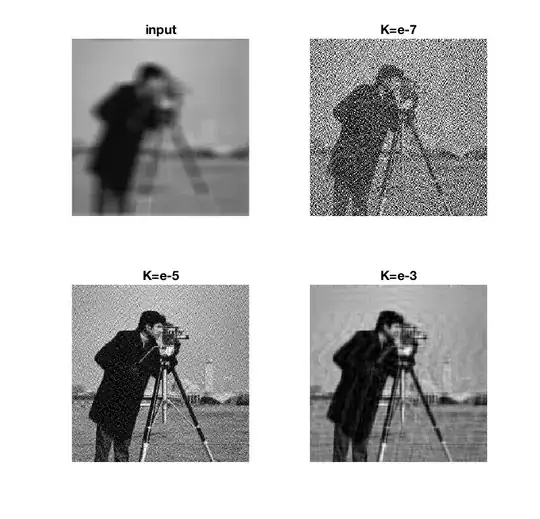
As you can see, selecting the right K is very important. If it is too low, there is not sufficient regularization. If it is too high then there are too many artefacts (insufficient deconvolution). This parameter K depends on the input image, though there are tricks to estimate it. Also, a simple filter like this can never perfectly undo a harsh blur like I put on here. More advanced iterative approaches are necessary to obtain a better deconvolution.

Estimating the kernel

Let's turn this around, and estimate psf from original and in. It is possible to do the division directly (equivalent to the Wiener filter with K=0), but the output is quite noisy. Where the original image has very low frequency-domain values, you'll get poor estimates. Picking the right K leads to a better estimate of the kernel. With a K that is too large, the result is again a poor approximation.

% Direct estimation by division
psf1 = fftshift(ifft2(fft2(in)./fft2(original)));

% Wiener filter approach
K = 1e-7;
H = fft2(original);
cH = conj(H);
HcH = H .* cH;
K = K * max(max(abs(HcH)));
w = cH ./ (HcH + K);
psf2 = fftshift(real(ifft2(w .* fft2(in))));

(zoom in to observe the noise)


Edit

I downloaded the images from the website you linked. I used the first result, without padding, and cropped the frames from the images as best as I could, to leave only the data and exactly the data:

original = imread('original.png');
original = original(33:374,120:460,1);

in = imread('blur_nopad.png');
in = in(33:374,120:460,1);

Then I used the code exactly as above, with the same K and everything, and got a pretty good result, showing a slightly shifted Gaussian kernel.

I then repeated the same with the second result (after padding) and got a worse result, but still very recognizable as a Gaussian.

Cris Luengo
  • 55,762
  • 10
  • 62
  • 120
  • I don't understand the purpose of this. The original image I had doesn't have noise, so that is not the issue – user5739619 Feb 16 '18 at 16:29
  • using `fft2` instead of `fft` in my original code gets rid of the NaN values. However, when I use `imshow` on the result of `conv`, it still shows a pure black image. All the values of `conv` are between +.05 and -.05. The actual filter has lots of zeros too, but there regions where it is clearly white and has values as high as 240. Why are the `conv` values so small? – user5739619 Feb 16 '18 at 16:30
  • the `conv` I use is a variable name for the computed filter. I don't use the Matlab `conv` operator – user5739619 Feb 16 '18 at 16:55
  • so the point of your code is to use `out` in place of `orig` and then compute `ifft2( fftblur / ifft2(out) )`, right? When I used your code, I got an error for `out = real(ifft2(w .* fft2(in)));` saying the matrix dimensions of `w` and `in` don't agree. – user5739619 Feb 16 '18 at 17:51
  • I forgot to mention that for my problem the original filter and the images don't have the same sizes. For example, the original and blurred images are 50x50 while the filter is 3x3. And yes, I did replace `/` by `./` – user5739619 Feb 16 '18 at 17:52
  • You need to expand the filter to the size of the images. `padarray`. – Cris Luengo Feb 16 '18 at 18:02
  • `padarray` fixed it. However, the result of `out` is numbers between .2 and -.2. If I then scale it so that the max value is 250, the result of `imshow` looks like the original blurred image. However, the computed filter still doesn't make sense. It's just a scatter of white and black pixels. The origina filter is mostly black pixels, with some white pixels in the middle – user5739619 Feb 16 '18 at 18:28
  • @user5739619: I've edited the answer to make the application to your problem more explicit, I hope you can now take the code you need. Do note that your blurring filter (`psf`) should sum up to 1, so small values are expected. – Cris Luengo Feb 17 '18 at 05:45
  • I got the code to work, but the output psf still seems wrong. The original blurred image had a 10x10 matrix of blurred square objects. The resulting psf shows an matrix of blurred square objects as well. Whereas the actual psf is supposed to be just one object will varying levels of grayscale pixels. Maybe it's because I need an additional step to reduce the computed psf from 50x50 to 3x3? If so, is there a way to "compress' the white pixels to the center? – user5739619 Feb 19 '18 at 17:57
  • @user5739619: I expect you need to tweak the K until you get the result you need. If your original kernel was 3x3, you should get a large black image back with a 3x3 region in the middle with non-zero values. (Of course the zero values have noise and so on too). Maybe you can post your images? – Cris Luengo Feb 19 '18 at 21:46
  • I did tweak the K's but that didn't help. I used some new images to try to make this easier. It is under "EDIT" in the original question – user5739619 Feb 19 '18 at 22:41
  • @user5739619: Using the images on that website I got pretty good results, see the edit in my answer. – Cris Luengo Feb 20 '18 at 00:10