3

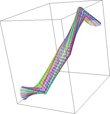
I am trying to generate a 3d tube along a spline. I have the coördinates of the spline (x1,y1,z1 - x2,y2,z2 - etc) which you can see in the illustration in yellow. At those points I need to generate circles, whose vertices are to be connected at a later stadium. The circles need to be perpendicular to the 'corners' of two line segments of the spline to form a correct tube. Note that the segments are kept low for illustration purpose.

[apparently I'm not allowed to post images so please view the image at this link] http://img191.imageshack.us/img191/6863/18720019.jpg

I am as far as being able to calculate the vertices of each ring at each point of the spline, but they are all on the same planar ie same angled. I need them to be rotated according to their 'legs' (which A & B are to C for instance).

I've been thinking this over and thought of the following:

  • two line segments can be seen as 2 vectors (in illustration A & B)
  • the corner (in illustraton C) is where a ring of vertices need to be calculated
  • I need to find the planar on which all of the vertices will reside
  • I then can use this planar (=vector?) to calculate new vectors from the center point, which is C
  • and find their x,y,z using radius * sin and cos

However, I'm really confused on the math part of this. I read about the dot product but that returns a scalar which I don't know how to apply in this case.

Can someone point me into the right direction?

[edit] To give a bit more info on the situation:

I need to construct a buffer of floats, which -in groups of 3- describe vertex positions and will be connected by OpenGL ES, given another buffer with indices to form polygons.

To give shape to the tube, I first created an array of floats, which -in groups of 3- describe control points in 3d space.

Then along with a variable for segment density, I pass these control points to a function that uses these control points to create a CatmullRom spline and returns this in the form of another array of floats which -again in groups of 3- describe vertices of the catmull rom spline.

On each of these vertices, I want to create a ring of vertices which also can differ in density (amount of smoothness / vertices per ring).

All former vertices (control points and those that describe the catmull rom spline) are discarded.

Only the vertices that form the tube rings will be passed to OpenGL, which in turn will connect those to form the final tube.

I am as far as being able to create the catmullrom spline, and create rings at the position of its vertices, however, they are all on a planars that are in the same angle, instead of following the splines path.

[/edit]

Thanks!

Dr. belisarius
  • 60,527
  • 15
  • 115
  • 190
Will Kru
  • 5,164
  • 3
  • 28
  • 41
  • Thanks! As I am very surprised about the expertise and activity on this forum, I will register an account and start sharing my knowledge too :) starting with 2) .. – Will Kru Dec 22 '10 at 02:42

4 Answers4

10

Suppose you have a parametric curve such as:

xx[t_] := Sin[t];
yy[t_] := Cos[t];
zz[t_] := t;  

Which gives: alt text

The tangent vector to our curve is formed by the derivatives in each direction. In our case

Tg[t_]:= {Cos[t], -Sin[t], 1}  

The orthogonal plane to that vector comes solving the implicit equation:

Tg[t].{x - xx[t], y - yy[t], z - zz[t]} == 0  

In our case this is:

-t + z + Cos[t] (x - Sin[t]) - (y - Cos[t]) Sin[t] == 0  

Now we find a circle in that plane, centered at the curve. i.e:

c[{x_, y_, z_, t_}] := (x - xx[t])^2 + (y - yy[t])^2 + (z - zz[t])^2 == r^2  

Solving both equations, you get the equation for the circles:

alt text

HTH!

Edit

And by drawing a lot of circles, you may get a (not efficient) tube:

alt text

Or with a good Graphics 3D library:

alt text

Edit

Since you insist :) here is a program to calculate the circle at junctions.

a = {1, 2, 3}; b = {3, 2, 1}; c = {2, 3, 4};
l1 = Line[{a, b}];
l2 = Line[{b, c}];

k = Cross[(b - a), (c - b)] + b; (*Cross Product*)
angle = -ArcCos[(a - b).(c - b)/(Norm[(a - b)] Norm[(c - b)])]/2;
q = RotationMatrix[angle, k - b].(a - b);
circle[t_] := (k - b)/Norm[k - b] Sin@t + (q)/Norm[q] Cos@t + b;

Show[{Graphics3D[{
    Red, l1,
    Blue, l2,
    Black, Line[{b, k}],
    Green, Line[{b, q + b}]}, Axes -> True],
  ParametricPlot3D[circle[t], {t, 0, 2 Pi}]}]

alt text

Edit

Here you have the mesh constructed by this method. It is not pretty, IMHO:

alt text

Dr. belisarius
  • 60,527
  • 15
  • 115
  • 190
  • I would upvote but apparently I need to harvest me some reputation first ;) In this case I am building a vertex buffer for the tube, which eventually needs to be rendered using OpenGL. So it's really about finding the vertices for each ring within the spline I define. I really appreciate the effort of your nicely illustrated answer, however I don't see how to link it to an array of [x,y,z] that defines the spline mentioned. – Will Kru Dec 22 '10 at 03:22
  • @Will The spline is basically a parametric curve. You just take the parametric equations for the spline and select where you want your circles. – Dr. belisarius Dec 22 '10 at 03:24
  • @belisarius I don't think it is parametric as there is no common variable. It's just an array with arbitrary numbers describing 3d vectices which OpenGL will connect later on. I was hoping there were just some easy steps to put the correct rotation into the part were I am creating the ring vertex coordinates. Could you direct me to the correct steps in this particular case? – Will Kru Dec 22 '10 at 19:43
  • @Will So your question is not clear, as you said in the first sentence that you have splines. And you don't mention OpenGL. Also OpenGL is not in your tags. Please re-phrase your question. Also: Calculating a spline is veeeery easy ... – Dr. belisarius Dec 22 '10 at 19:47
  • @Will Also: beware. Tubes constructed your way may not contain the spline, as they will route straight through vertex, and the splines will not – Dr. belisarius Dec 22 '10 at 20:10
  • @belisarius I create a catmullrom spline, which will always travel through the control points themselves. In the image you could think of the spline with density 1, ie just the control points. – Will Kru Dec 22 '10 at 20:55
  • @belisarius Thanks, I'm gonna look into that! – Will Kru Dec 22 '10 at 22:59
  • @belisarius It indeeds seems to suffer from the twisting that would be prevented by the Frenet frame.. [edit] but wasn't your calculation based on that..? Also, the ring doesn't seem centered between the two 'legs' – Will Kru Dec 23 '10 at 00:52
  • @Will I did nothing to prevent twisting (Perhaps I could, but I was thinking in the other approach). Also note that as the circles are not in parallel planes, the tubes are not of constant radius (nor really circular) – Dr. belisarius Dec 23 '10 at 00:57
  • @Will The rings are centered, but the visual effect is odd. – Dr. belisarius Dec 23 '10 at 01:25
  • I'm closing this one, thanks for your extensive reply and pointing me into the right direction. I ended up using the Parallel Transport Frame. I got my circles following the spline just fine now. Final thing is to boost them another 90 degrees. Final result here: http://img838.imageshack.us/img838/4315/rotation.jpg THANKS! – Will Kru Dec 24 '10 at 02:26
  • @Will Looks good! Keep in mind that sometimes is easier to rotate things at the origin, and the go back to the original position. You have to re-orient the circles in the direction of the tangent line. Good luck! – Dr. belisarius Dec 24 '10 at 02:32
  • Got it, I had to go from [X,Y,Z] to [X,Z,Y] in my ring vertex calculations http://img189.imageshack.us/img189/7461/rotationm.jpg – Will Kru Dec 24 '10 at 03:37
  • @Will Wow ... almost there! congrats! – Dr. belisarius Dec 24 '10 at 04:17
1

You need to look at Fenet formulas in Differential Geometry. See figure 2.1 for an example with a helix.

Surfaces & Curves

Martin
  • 157
  • 1
  • 3
  • 8
John Alexiou
  • 28,472
  • 11
  • 77
  • 133
1

I don't know what your language of choice is, but if you speak MatLab there are already a few implementations available. Even if you are using another language, some of the code might be clear enough to inspire a reimplementation.

The key point is that if you don't want your tube to twist when you connect the vertices, you cannot determine the basis locally, but need to propagate it along the curve. The Frenet frame, as proposed by jalexiou, is one option but simpler stuff works fine as well.

I did a simple MatLab implementation called tubeplot.m in my formative years (based on a simple non-Frenet propagation), and googling it, I can see that Anders Sandberg from kth.se has done a (re?)implementation with the same name, available at http://www.nada.kth.se/~asa/Ray/Tubeplot/tubeplot.html.

TubePlot.m illustration

Edit: The following is pseudocode for the simple implementation in tubeplot.m. I have found it to be quite robust.

The plan is to propagate two normals a and b along the curve, so that at each point on the curve a, b and the tangent to the curve will form an orthogonal basis which is "as close as possible" to the basis used in the previous point. Using this basis we can find points on the circumference of the tube.

// *** Input/output ***
// v[0]..v[N-1]: Points on your curve as vectors
//               No neighbours should overlap
// nvert: Number of vertices around tube, integer.
// rtube: Radius of tube, float.
// xyz: (N, nvert)-array with vertices of the tube as vectors


// *** Initialization ***
// 1: Tangent vectors
for i=1 to N-2:
    dv[i]=v[i+1]-v[i-1]
dv[0]=v[1]-v[0], dv[N-1]=v[N-1]-v[N-2]

// 2: An initial value for a (must not be pararllel to dv[0]):
idx=<index of smallest component of abs(dv[0])>
a=[0,0,0], a[idx]=1.0

// *** Loop ***
for i = 0 to N-1:
    b=normalize(cross(a,dv[i]));
    a=normalize(cross(dv[i],b));
    for j = 0 to nvert-1:
        th=j*2*pi/nvert 
        xyz[i,j]=v[i] + cos(th)*rtube*a + sin(th)*rtube*b

Implementation details: You can probably speed up things by precalculating the cos and sin. Also, to get a robust performance, you should fuse input points closer than, say, 0.1*rtube, or a least test that all the dv vectors are non-zero.

HTH

Janus
  • 5,421
  • 2
  • 26
  • 37
  • It's JAVA on the Android platform. This really looks exactly like the thing i'm after, but the .m files are unreadable to me as it doesn't seem like common code. – Will Kru Dec 22 '10 at 19:46
0

Taking the cross product of the line segment and the up vector will give you a vector at right-angles to them both (unless the line segment points exactly up or down) which I'll call horizontal. Taking the cross product of horizontal and the line segment with give you another vector that's at right angles to the line segment and the other one (let's call it vertical). You can then get the circle coords by lineStart + cos theta * horizontal + sin theta * vertical for theta in 0 - 2Pi.

Edit: To get the points for the mid-point between two segments, use the sum of the two line segment vectors to find the average.

Jackson Pope
  • 14,520
  • 6
  • 56
  • 80