0

Although I have completed a university course in digital logic, I am new to VHDL design and I am hoping if someone can help me create 2 clock signals which depend on the state of one another.

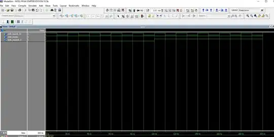
I am using a 50 MHz clock on a DE2-115 FPGA board that is used to create a 5MHz clock (named dclk_5). However, the simulation is showing the two signal but only up to 200 ns of run time and won't run any longer. Why doesnt the simulation run longer than 200 ns?

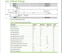
datasheet of the 2 clocks:

https://gyazo.com/485e354bf8cfef984757e2014fa8fde3

Alternative VHDL Design for testing dclk_5 and clk_50 which synthesizes but simulation is not correct:

library ieee;
use ieee.std_logic_1164.all;
use ieee.numeric_std.all;

entity DCLK_top is
port(
    clk_50  : in std_logic;
    sw         : in std_logic;
    dclk_5  : out std_logic
);

end DCLK_top;

architecture behaviour of DCLK_top is
    signal clk_counter          : integer range 0 to 10 := 0;
    signal dclk_counter         : integer range 0 to 8  := 0;
    signal dclk_pause_counter   : integer range 0 to 7  := 0;

    signal dclk_pause               : std_logic := '0';
    signal clk_pause_counter    : integer range 0 to 7 := 0;

begin
    dclk_proc : process(clk_50)
    begin

        if(clk_50'event and clk_50='1' ) then
            clk_counter <= clk_counter+1;

            if(clk_counter=10) then
                clk_counter <= 0;
            end if;

            if(clk_counter<5) then
                dclk_5 <= '0';
            else
                dclk_5 <= '1';
            end if;
        end if;

    end process dclk_proc;
end architecture behaviour; 

Picture of simulation:

https://gyazo.com/ad902a9a8066144692f2672484672b8d

MrMuffins
  • 25
  • 1
  • 7
  • I don't know much about Quartus but isn't there any tool to generate clocks like xilinx? You neither explain what is your exact problem... the code seems synthesizable.... I would put `start_dclk = '1'` in another `if`. – ferdepe Feb 14 '17 at 20:50
  • I used ModelSim to generate the clock but the issue is that the 50MHz would run normally for any amount of time by itself but when I include the dclk (5MHz), the entire simulation would stop after 400ns which is 1 dclk cycle. So I was assuming the problem is within my design. I will also update the post with screen shots of the simulation. – MrMuffins Feb 14 '17 at 21:01
  • Your question is unclear, what are the results and what are the expected results? See [How do I ask a good question?](https://stackoverflow.com/help/how-to-ask) and [How to create a Minimal, Complete, and Verifiable example](https://stackoverflow.com/help/mcve). Originally addressed as [Quartus VHDL ModelSim not showing what I want](http://electronics.stackexchange.com/questions/286307/quartus-vhdl-modelsim-not-showing-what-i-want) on Electrical Engineering Stack Exchange, question guidelines are different on Stack Overflow. –  Feb 14 '17 at 21:02
  • Take a look to the signal assignment. Under simulation, normally, the signal is not updated until the process is finished. I advise you to use variables. With variables the values are updated instantly, with signals... you have to wait a delta time. However... I haven't under stood the problem yet.. How do you run Modelsim? Which signals are you monitoring? Does Modelsim give you a error message? follow @user1155120 advice. Split your code and do an incremental testing. – ferdepe Feb 14 '17 at 21:15
  • Sorry I was asking too many questions. I refined the question so I'm only asking about the main problem that is stopping me from progressing. In addition, the "sw" signal does not affect the design, it was added in by accident. – MrMuffins Feb 14 '17 at 21:30
  • 1
    You might want to use `rising_edge(clk_50)` instead of `clk_50'event and clk_50='1'` – scary_jeff Feb 15 '17 at 09:31
  • The solution is ok for simulation, however, do not expect that you can simply clock items between your generated dclk_5 and Clk_50. The clocks will not have a known or even stable phase relationship. If you are not clocking things between the two clock domains it is ok. Otherwise, while I prefer code solutions for everything, this is one place I recommend using a clock macro or a clock wizard - surely your FPGA vendor will have something that does this. – Jim Lewis Feb 15 '17 at 17:34

1 Answers1

1

Well, your code in not that bad, but there is one problem.

clk_counter <= clk_counter+1;
if(clk_counter=10) then
    clk_counter <= 0;
end if;

So the <= assignment is not assigned until the end of the process. So clk_counter is 9 for the whole process. It will be set to 10, but not until the end of the process, so the if-statement does not trigger. So the next evaluation of the process, clk_counter is 10. Now the if-statement /will/ trigger. However, before that you want to assign 10+1 = 11 to clk_counter.... But that is not allowed, because the range of clk_counter is 0 to 10. You could set the range to 11 and this will not happen. but then the code does not do what you want it to do. So, cleaner code is better imho. E.g.:

if(clk_counter<10) then
    clk_counter <= clk_counter+1;
else
    clk_counter <= 0;
end if;

You could also separate the assignment of dclk from the process. E.g.:

dclk <= '0' when (clk_counter<5) else '1';

But this is not glitch friendly. You should preferably clock your assignment, like you are already doing.

JHBonarius
  • 10,824
  • 3
  • 22
  • 41
  • p.s. next time please report the error message: modelsim will report an error when assigning 11 to a range 0 to 10 signal. Error messages are very important! They could already help you solve you own problem.... – JHBonarius Feb 15 '17 at 10:19
  • If you look at the wave, `dclk` is activated at the sixth clock despite of being activated in the fifth. That is what your answer solves and don't solve the problem with the simulator. However, I don't know much Modelsim, but in ISim `range` assignments are deprecated. – ferdepe Feb 15 '17 at 11:55
  • Yes, of course it does. That is because clk_count changes to 5 on one clock, but is detected by (clk_count<5) is the next trigger of the process. as dclk is clocked, it is assigned a clock period later. But that should not be a big deal. Could you link to a statement where range assignment is deprecated? Because I don't know about that: range is perfectly good VHDL, sometimes even required to prevent integer as resulting in 32-bit registers in implementation. – JHBonarius Feb 15 '17 at 12:17
  • it works! I changed the if statement you mentioned, the clk_counter range was also changed to 9 and now it works. Thanks for the help! – MrMuffins Feb 15 '17 at 17:04