-1

I am posting this question after not getting any sort of help across the web and reading many articles and tutorials. I ended up asking questions with hope of getting guided. DESPERATE FOR HELP.

What i want: 1) I want to build a R/C tank. 2) Basically its not controlled by a remote control but i want control by a laptop.(i could write a c++ or c# program).

What i know: 1) I know how to develop a development board. (i want to develop my own, not use arduino) 2) I know c++ and assembly very well. 3) I know about AVR's ALU, Memories(all 3), Stack, Interrupts, IO Operations well. 4) I know theory about how SPI, RS232, UART works.

PROBLEMS: (I have many questions, but most important are) 1) B/c i have made my own board. How can i transfer my program(hex file) to my board(i seek practical and physical implementation, not theory please)(i know about a 6-pin ISP but not clear about practical implementation) 2) After it, how can i make wireless communication b/w my AVR and laptop.(hardware device?)(SPI, RS232, UART?)

MAIN CONFUSION: 1) I cannot help myself differentiating or relating SPI, RS232 and UART. I know these are used for serial communication between devices but how?(which is used when and why and how)(appropriate hardware for transmitting device and receiving device)

THING TO KNOW: 1) I haven't started making my board and programming it because i think i should learn everything first and then do it in a one go. OR should i start practical work and things get easier automatically?? 2) I learnt a tutorial series on Serial Communication from http://maxembedded.com/2013/09/serial-communication-introduction/ the starting 5 topics leaving the last one(I2C). Am i missing something there?

I hope everything is clear, and waiting for a good-men's words.

Note: I am already very misguided and lost, so i want experienced and expert's guidance. Many Many Many Many Thanks in Advance.

MY BOARD LOOKS LIKE: http://www.robotplatform.com/howto/dev_board/schematic_l/38.jpg
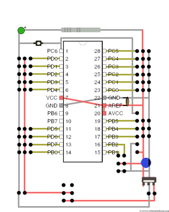
1 Answers1

2

1) To upload your code into AVR chip, you can use ISP interface. That requires you to connect at least 5 pins: SCK, MISO, MOSI, RESET, GND, and optionally VCC (it used to control or supply voltage, but not mandatory, if your board has it's own power supply). All you need is just to wire 6- or 10-pin ISP connector to that pins of your CPU. To begin programming process you need to obtain some programmer device (USBasp, AVRISPmk2, STK500/600 etc.), Also, you can use Arduino board itself as ISP-programmer for external AVR chip, like this: http://www.instructables.com/id/Programming-an-ATTiny13A-using-Arduino-servo-int/ Each of programmer model requires it's compatible software (such as PonyProg), for example STK500 and AVRISP programmes could be used directly from Atmel Studio. Also, you can connect ISP to parallel (LPT) port of the PC, and upload firmware using specialized software, such as uniprof

Another way to upload software - it is to make your own bootloader - a tiny program that will update firmware, using any available interface.

2) USART, SPI, I2C - it is different interfaces to communicate with peripherals. Note that RS232 - it is electrical interface built over USART. I.e. you need external IC which will convert USART logical level signals to RS232 electrical levels.

each of that interfaces have it's own profs and cons. And usually selection of which interface to use depends on which interface is supported by peripherals.

SPI - it is interface for high-speed communication. One master many slaves. It requires a lot of wires: MISO (data from master to slave), MOSI (data from slave to master), SCK (clock) - those three could be common for all slaves. Also it requires a SS (slave select) - one SS wire for each slave to determine which slave is in communication at the moment, also it sets the edges of the data packet.

USART - it is common interface, to communicate two chips. Each byte transmitted with foregoing start bit, optional parity and following stop bit. I.e. transfer has a quarter overhead, but byte can be transmitted in any moment.

Works in synchronous and asynchronous modes. Asynchronous mode requires only 2 wires (RX and TX, not counting GND that also required). This mode requires that receiver and transmitter to be sychronized, in most cases that required to crystal oscillator to be installed.

Synchronous mode works in the same format as asynchronous, but have additional XCK (clock) wire, that determines in which moments bits are possible to be transmitted. This allows to increase transmission speed and not requires time precision from receiver. Synchronous mode is rare used.

I2C - it's a bus with only two wires, allows many masters and many slaves. Utilizes pull-up resistors to achieve wired AND, have it's own algorithm to detect collisions, more complicated to be programmed, transmission speed is limited. Often used by peripherals, such as accelerometers, RTCs etc.

AVR chips have no it's own support for wireless communication, therefore, to do that you need to use some external wireless chip, for example bluetooth, or WiFi, there are a lot of such modules (for example ESP8266). AVR chip communicate with them using USART, sending and receiving simple commands.

AterLux
  • 4,566
  • 2
  • 10
  • 13