4

I know what the inout parameters is and how to use them. Assume that we have an inout parameter io and want to create a bidirectional static RAM such as the following code :

LIBRARY ieee;
USE ieee.std_logic_1164.ALL;

ENTITY sram IS
    port(
        clk  : IN    std_logic;
        wr   : IN    std_logic;
        io   : INOUT std_logic;
        addr : IN    INTEGER RANGE 0 TO 7
    );
END sram;

ARCHITECTURE behavioral OF sram IS
    TYPE matrix IS ARRAY (0 TO 7) OF std_logic;
    SIGNAL mem : matrix;
BEGIN
    PROCESS(clk)
    BEGIN
        IF rising_edge(clk) THEN
            IF wr = '1' THEN
                mem(addr) <= io;
            END IF;
        END IF;
    END PROCESS;
    io <= mem(addr) WHEN wr = '0' ELSE 'Z';
END behavioral;

We can create an instance of sram and write on it such as the following code :

io <= '1' WHEN wr = '1' ELSE 'Z';

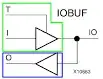
Question : How can synthesis tool control the multiple assignments and judge between multiple drivers ? What hardware is implemented to do it ?


Thanks for comments and answers ...

Amir
  • 507
  • 3
  • 12
  • Who's the silicon vendor? The reason for the question is, that if tristate buses aren't supported the question is moot. –  Jan 02 '15 at 10:00
  • The rules for how to deal with 'Z' are found in the now rescinded IEEE Std 1076.6-2004, 6.3 Three-state logic and buses, 6.3.1 Three-state logic from 'Z' assignment, 6.3.2 Three-state logic from guard disconnect. An example of a RAM with a three-state output is shown in Examples 2 and 3 in 6.5.2 Random-access memory (RAM). You'd be hard pressed to find a silicon vendor who allows bidirectional buses. Neither RAM example uses one. Historically you were required to have an active terminator on an ASIC three state bus. A chip edge with a bidir buffer would have an in port and out port. –  Jan 02 '15 at 10:16
  • Thank you David. Do you mean I can do it on an ASIC three state bus with a bidirectional buffer? Is it supported inside a chip or it's just for IO pins? – Amir Jan 02 '15 at 11:47
  • Tristate buses (internal to an FPGA) in HDL can often be transformed by the synthesis tool into an equivalent structure (separate in and out signals, and multiplexers). But if the synth tool can't find an equivalent, it will report an error instead. If (a) this happens or (b) if you care about the size of the resulting huge mass of logic it's better to rewrite explicitly with separate In and Out ports. –  Jan 02 '15 at 12:08

2 Answers2

3

For typical FPGA and ASIC devices, implementation of tristate capabilities are only available on the IO, like for example in an Altera Arria 10 FPGA:

enter image description here

So for such devices, the internal RAMs are always implemented with dedicated input and output ports, thus not using any internal tristate capabilities.

Even if a RAM is connected to external IOs that support tristate, then the internal RAM block is still typically created with dedicated input and output ports, so the connection to a tristate capable pin on the device is handled through an in-out buffer with the output enable and tristate capability.

If internal design tries to use tristate capabilities or multiple drivers when this is not supported by the device, then the synthesis tool will generate and error, typically saying that multiple drivers are not supported for the same net.

Morten Zilmer
  • 15,586
  • 3
  • 30
  • 49
  • Thanks Morten. Do you mean I never can implement a bidirectional RAM inside the chip and just some devices support it on the IO? Do you think xilinx spartan3 (3s400) support it? – Amir Jan 02 '15 at 11:48
  • Xilinx Spartan-3 does not support on-chip bidirectional signals; only bidirectional IOs. In the early ages of ASICs and FPGAs, on-chip bidirectional signals were used, since it was possible to save gates when muxes could be avoided on busses. But the on-chip bidirectional signals where difficult to test with scan chains, and had the risk of conflicting drivers causing current spikes and thus voltage drops, so use of on-chip bidirectional signals was abandoned when gates got plenty and bus timing was not the critical path. – Morten Zilmer Jan 02 '15 at 12:42
  • Thanks a lot Morten. You helped me a lot. – Amir Jan 02 '15 at 12:57
3

On Xilinx devices, the schematics are similar.

This is an image of primitive IOBUF:
IOBUF

The green part is the output driver with tristate control; the blue part is the input driver. The complete IOB (Input/Output Block) consists of several primitives:

  • IOB registers (input, output, tristate control)
  • delay chains
  • wires to combine two IOBs to a differential IOB (**BUFDS)
  • capability to drive clock networks (CC-IOB - clock capable IOB)
  • pullup, pulldown, ...
  • driver (IOBUF)
  • pin/ball (IPAD, OPAD, IOPAD) - this includes ESD protection

How does synthesis work?

  • Xilinx synthesis tools (XST / Synth) add IPAD or OPAD primitives for every wire in your top-level component's port description. A pad is just the primitive to represent a physical pin or ball under the FPGA package.
  • If you enabled to automatically add I/O buffers, the tool will add IBUF, OBUF, IOBUF, IBUFDS, ... primitives between every PAD and top-level port. It uses the port direction (in, out, inout) to infer the correct buffer type. If this option is disabled (default = on) you have to manually add buffers for every I/O pin. In some cases XST gets offended: I added some IOBUFs with tristate control by hand so XST declined to infer the missing buffers. So I had to add all buffers by hand ...

While using Xilinx XST it's possible to use tristate buses (port direction = inout) beneath the top-level. XST will report that it added (virtual) tristate buffers. These buffers get trimmed if the direction of each bit of the bus has an obvious direction and no multiple driver problem.

This does not work in iSim.

Community
  • 1
  • 1
Paebbels
  • 15,573
  • 13
  • 70
  • 139