-2

I have this LFSR and I am unsure how to find the polynomial associated with it. I am trying to create a _static _flash look up table with uint8_t variables to save on computing cycles. Only problem, I'm not sure how to implement an LFSR in C++.

Cheers, Hearny

Hearny
  • 17
  • 3

1 Answers1

0

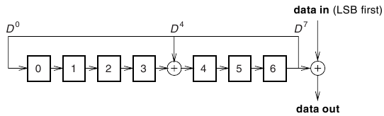
The latches are labeled 0 through 6. The latches are shifted right 1 latch, and the value that was in latch 6 before the shift is placed into latch 0 and xor'ed with latch 4 (the value that ends up in latch 4 is the xor of the prior latch 3 and latch 6).

For the polynomial, it's not clear if the left latch or the right latch is considered to be the most significant latch (bit). The hardware diagram shows a right shift, but that diagram could be reversed, shifting left instead of right, still using D6 to xor into the data bit stream.

The diagram is a bit confusing, since it shows D0, D4, and D7, but there are only 7 bits, not 8.

This LFSR will cycle through all 127 possible non-zero 7 bit values before repeating. Here is a table of the cycle pattern, shown in hex:

01,44,22,11,4c,26,13,4d,62,31,5c,2e,17,4f,63,75
7e,3f,5b,69,70,38,1c,0e,07,47,67,77,7f,7b,79,78
3c,1e,0f,43,65,76,3b,59,68,34,1a,0d,42,21,54,2a
15,4e,27,57,6f,73,7d,7a,3d,5a,2d,52,29,50,28,14
0a,05,46,23,55,6e,37,5f,6b,71,7c,3e,1f,4b,61,74
3a,1d,4a,25,56,2b,51,6c,36,1b,49,60,30,18,0c,06
03,45,66,33,5d,6a,35,5e,2f,53,6d,72,39,58,2c,16
0b,41,64,32,19,48,24,12,09,40,20,10,08,04,02

The C code for implementing one cycle of this lfsr using the int variable i:

    i = ((i&1)<<6)^((i&1)<<2)^(i>>1);

You didn't include what the starting value is, but just assume it's hex 01 as shown in my example table. Data is encrypted or decrypted by xor'ing latch D6 from the lfsr with symbol data bits, least significant data bit to most significant data bit. I think you only need to create a table of 127 n bit patterns. I confirmed this is true for 8 bit and 16 bit data. The table for 8 bit data:

c9,f2,0e,7f,dc,28,7d,15
da,73,6a,06,5b,17,13,81
64,79,87,3f,6e,94,be,0a
ed,39,35,83,ad,8b,89,40
b2,bc,c3,1f,37,4a,5f,85
f6,9c,9a,c1,d6,c5,44,20
59,de,e1,8f,1b,a5,af,42
7b,4e,cd,60,eb,62,22,90
2c,ef,f0,c7,8d,d2,57,a1
3d,a7,66,b0,75,31,11,48
96,77,f8,e3,46,e9,ab,d0
9e,53,33,d8,ba,98,08,24
cb,3b,fc,71,a3,f4,55,68
cf,a9,19,6c,5d,4c,04,92
e5,1d,fe,b8,51,fa,2a,b4
e7,d4,0c,b6,2e,26,02

As an attempt to explain the polynomial, reverse the LFSR, so D[6] is on the left, and D[0] is on the right. Start with an initial value of 1000000 and perform a Galois polynomial divide (xor is used instead of subtract) by 10010001 (D^7 + D^4 + 1), appending zeroes as needed to cycle (shift) the LFSR

10010001 | 1000000        (01 reversed)
           10010001       (D^7 + D^4 + 1)
            -------
            0010001       (44 reversed)
             0100010      (22 reversed)
              1000100     (11 reversed)
              10010001    (D^7 + D^4 + 1)
               -------
               0011001    (4c reversed)
rcgldr
  • 27,407
  • 3
  • 36
  • 61
  • Wow, thank you for such a detailed explanation! I apologize about the lack of initial conditions, the input into the LFSR is a 6 bit unknown combination. Excuse my ignorance but will I have to assume that there will be 64 possible input combinations and therefore 64 possible output combinations **OR** will the contents be constant just placed differently within the input and output tables? Again, thank you – Hearny Oct 05 '14 at 11:37
  • The diagram showed a 7 bit setup, 7 latches labeled D0 through D6. There is no external input other than the initial state. The LFSR cycles through 127 seven bit patterns in the order shown in the first table I posted above. The output consists of XOR'ing D6 with data bits to encrypt or decrypt data. The second table shows the XOR output pattern assuming an initial state of 01. Note the lsb of the first 8 entries in the first table is 1 0 0 1 0 0 1 1, since data is xor'ed lsb to msb, I reversed this to end up with C9. The next byte would get F2. The pattern cycles every 127 bytes. – rcgldr Oct 06 '14 at 00:35
  • I see what you're saying about the 7 bit setup. This [image](http://i.imgur.com/baS0V5Q) taken from Bluetooth Specs v1.2 agrees with your deductions. The polynomial of the LFSR is stated to be D7 + D4 + 1. This [image](http://i.imgur.com/ThUwxwk) however, someone else's work insinuates that it would be a 6 bit LFSR (2^6 = 64). I understand how the 127 patterns are obtained, and if Im correct if the input or value to XOR with is binary, there can only be a 0 or 1 bit to be XOR'd with therefore there will be a total of 254 output values or either 1 or 0 with the original 127 states? – Hearny Oct 06 '14 at 12:00
  • The diagram of the LFSR is lsb to msb left to right. Each LFSR cycle is a multiply by 2 modulo the 8 bit polynomial D^7 + D^4 + 1, which produces a 7 bit remainder (including leading zeroes). There are only 64 initial states because D[6] is always set to 1, and the remaining 6 bits are set D[5] = CLK[6], D[4] = CLK[5], ..., D[0] = CLK[1]. Data is encrypted or decrypted by xor'ing D[6] with each data bit, lsb to msb, then cycling the LFSR. For an n bit data element, the LFSR is cycled n times, and as in the second image, there are only 127 possible n bit values to xor to each element. – rcgldr Oct 06 '14 at 12:58
  • The first image mentions reducing DC bias with the LFSR pattern, but if the data pattern is similar to the LFSR pattern, you still get a DC bias. To remove a DC bias, you need something similar to [8 to 10 bit encoding](http://en.wikipedia.org/wiki/8b/10b_encoding) (wiki link). The second image mentions using a CRC, but does not explain what the CRC polynomial is and how it's implemented (lsb to msb or msb to lsb). – rcgldr Oct 07 '14 at 00:46
  • Ok, I am reading these and I think it is confusing me because I may have a false understanding of an LFSR. I had an attempt at it by [hand](http://i.imgur.com/RR7fzkd). I understand how the polynomial works, but I have trouble understanding the 7 bit remainder and why D[6] is always set to 1. I think once I have this understood properly I should understand how to reverse this process. I am trying to build a table of the original LFSR encryption process so if I was to perform the decryption I could match it against the initial parameters. – Hearny Oct 07 '14 at 10:08
  • I would also like to present your authorship in my references in my scientific journal but I am unsure how to personal message you for your contribution. Again, thank you sincerely – Hearny Oct 07 '14 at 10:10
  • D[6] is not always set to 1, it's only set during initialization. The initial state of the LFSR is D[0] = CLK[1], D[1] = CLK[2], ... , D[5] = CLK[6], D[6] = 1. After this one time initialization, the LFSR never gets any external inputs again and just cycles through a repeating set of 127 seven bit patterns. – rcgldr Oct 07 '14 at 18:45
  • The modulo polynomial D^7 + D^4 + 1 is a bit harder to explain. I added an example in my answer above. During a LFSR cycle, what would be D[7] is instead stored into D[0] (the D^7 + 1 part), and xor'ed with D[3] and stored into D[4] (the D^4 part). Note there is no D[7] in the actual LFSR. It would be easier just to follow the LFSR diagram, or the C code for one cycle: i = ((i&1)<<6)^((i&1)<<2)^(i>>1); . – rcgldr Oct 07 '14 at 19:13