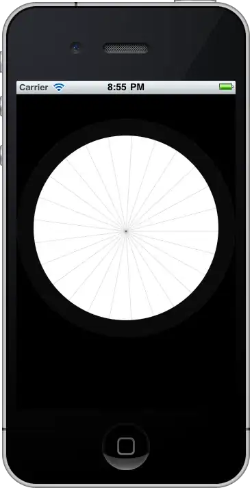
Hi, i'm coding the main program structure for my LCM, called DE2_LCM2(in vhdl).
Within the main structure, there is a clock divider calls PLL2 (in verilog) and a I2S_LCM_Config (in verilog). My PLL2.v and I2S_LCM.v are given by vendor, except for my DE2_LCM.vhd, myself coded. Compile successful, but stimulation failed.
FYI:
Horizontal scan:
1 Horizontal Line, there are 1171 counts or cycles of DCLK. The LCM_HSYNC goes low during falling edge of DCLK for 1 cycle. For the first 152 cycle, the data on LCM_DATA bus are invalid, start valid from cycle 153 to 1112, and invalid from cycle 1112 to 1171.
Vertical scan (Non-interlace):
After the last cycle of a horizontal line, the vertical counter shall be incremented by one. This LCM got 262 vertical lines in total, but only line 15 to (15+240)=255 is displayed.
LCM_PLL.v:
This file helps to convert system clock 50MHz to 18.42MHz. the DCLK or LCM_DCLK will be used for horizontal and vertical counter.
Below is my DE2_LCM.vhd codes, can't find what is going wrong on my code. Some more my teacher is on leave.
library ieee;
use ieee.std_logic_1164.all;
use IEEE.std_logic_unsigned.all;

entity DE2_LCM2 is port(CLOCK_50 : in std_logic;
                   KEY0 : in std_logic;
                   SW : in std_logic_vector(1 downto 0);
                   LCM_DATA : out std_logic_vector(7 downto 0);
                   LCM_DCLK, LCM_HSYNC, LCM_VSYNC,LCM_SCLK,LCM_SDAT,LCM_SCEN,LCM_GRST,LCM_SHDB : out std_logic
                    );
end DE2_LCM2;

architecture rtl of DE2_LCM2 is
  constant H_SYNC_CYC: integer:=1;
  constant H_SYNC_BACK: integer:=152;
  constant H_SYNC_ACT: integer:=960;
  constant H_SYNC_FRONT: integer:=59;
  constant H_SYNC_TOTAL: integer:=1171;

  constant V_SYNC_CYC: integer:=1;
  constant V_SYNC_BACK: integer:=14;
  constant V_SYNC_ACT: integer:=240;
  constant V_SYNC_FRONT: integer:=8;
  constant V_SYNC_TOTAL: integer:=262;

  signal H_Cont: std_logic_vector(10 downto 0);
  signal V_Cont: std_logic_vector(10 downto 0);
  signal MOD_CNT: std_logic_vector(1 downto 0);
  signal Tmp_DATA1: std_logic_vector(11 downto 0);
  signal CLK_18: std_logic;
  signal mSEL: std_logic_vector(1 downto 0);
  signal iRST_N: std_logic;
  signal I2S_SDAT: std_logic;

component LCM_PLL2 port(inclk0: in std_logic;
                      c0: out std_logic);
end component;

component I2S_LCM_Config is port(iCLK: in std_logic;
                             iRST_N: in std_logic;
                             I2S_SCLK: out std_logic;
                             I2S_SDAT: inout std_logic;
                             I2S_SCEN: out std_logic);
end component;

begin
  LCM_GRST<=KEY0;
  LCM_DCLK<=not(CLK_18);
  LCM_SHDB<='1';
  iRST_N<=KEY0;
  LCM_SDAT<=I2S_SDAT; --add on

  process(SW,MOD_CNT )
    begin
      if(SW="00")then
        if(MOD_CNT="00")then
          LCM_DATA<="01111111";
        else LCM_DATA<="00000000";
        end if;
      elsif(SW="01")then
        if(MOD_CNT="01")then
          LCM_DATA<="01111111";
            else LCM_DATA<="00000000";
        end if;
      elsif(SW="10")then
        if(MOD_CNT="10")then
          LCM_DATA<="01111111";
        else LCM_DATA<="00000000";
        end if;
      else LCM_DATA<="00000000";
      end if;
  end process;

u0:LCM_PLL2 port map(inclk0=>CLOCK_50,
                c0=>CLK_18);
u1:I2S_LCM_Config port map(iCLK=>CLOCK_50,
                       iRST_N=>KEY0,
                       I2S_SCLK=>LCM_SCLK,
                       I2S_SDAT=>I2S_SDAT,
                       I2S_SCEN=>LCM_SCEN);

process(CLK_18,iRST_N)
  begin
    if(rising_edge(CLK_18))then
      if iRST_N = '0'then
      MOD_CNT <= "11";
      H_Cont <= "00000000000";
      LCM_HSYNC <= '0';
      V_Cont <= "00000000000";
      LCM_VSYNC <= '0';
      else
        if((H_Cont >= H_SYNC_BACK) and (H_Cont<(H_SYNC_TOTAL-H_SYNC_FRONT)))then
          if(MOD_CNT < "10") then
          MOD_CNT <= MOD_CNT + '1';
          else
          MOD_CNT <= "00";
          end if;
        else MOD_CNT <= "11";
        end if;

        if(H_Cont < (H_SYNC_TOTAL-1)) then
        H_Cont <= H_Cont + '1';
        else H_cont <= "00000000000";
        end if;

        if(H_Cont < H_SYNC_CYC)then
        LCM_HSYNC <= '0';
        else LCM_HSYNC <= '1';
        end if;

        if(V_Cont <(V_SYNC_TOTAL-1)) then
          V_Cont <= V_Cont+'1';
        else V_Cont <= "00000000000";
        end if;

        if(V_Cont < V_SYNC_CYC) then
        LCM_VSYNC <= '0';
        else LCM_VSYNC <= '1';
        end if;
      end if;
    end if;
end process;
end rtl;
Should be my coding style that is not suitable for hardware programming. Do let me know if PLL2.v and I2S_LCM_Config.v are needed for your testing. I'll send u through email.
Thanks in advance:)