I'm trying to write a YUV to RGB shader in HLSL. Specifically, it converts the Yuv420p format which consists of an NM plane of Y values, followed by an (N/2)(M/2) plane of U values and then an (N/2)*(M/2) plane of V values. For example this 1280x720 picture:

looks like this in YUV format interpreted as an 8-bit, 1280x1080 texture:

In Direct3D11, I'm loading this as a Texture2D with format R8_UNorm and dimensions 1280x1080. The tricky part is reconstituting the U and V planes, because as you can see, half the lines are on the left side of the texture, and the other half is on the right side. In the shader, I do this like so:
struct PS_IN
{
    float4 pos : SV_POSITION;
    float2 tex : TEXCOORD;
};

Texture2D picture;
SamplerState pictureSampler;

float4 PS(PS_IN input) : SV_Target
{
    int pixelCoord = input.tex.y * 720;
    bool evenRow = (pixelCoord / 2) % 2 == 0;

    //(...) illustrating U values:
    float ux = input.tex.x / 2.0;
    float uy = input.tex.y / 6.0 + (4.0 / 6.0);
    if (!evenRow)
    {
        ux += 0.5;
    }

    float u = picture.Sample(pictureSampler, float2(ux, uy)).r;
    u *= 255.0;

    // for debug purposes, display just the U values
    float4 rgb;
    rgb.r = u;//y + (1.402 * (v - 128.0));
    rgb.g = u;//y - (0.344 * (u - 128.0)) - (0.714 * (v - 128.0));
    rgb.b = u;//y + (1.772 * (u - 128.0));
    rgb.a = 255.0;

    return rgb / 255.0;
}
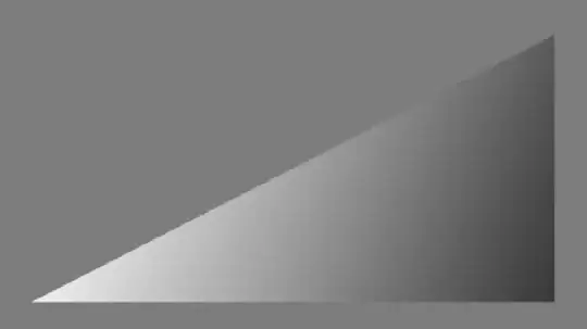
However, for some strange reason, this seems to produce a weird horizontal pattern of smeared edges:

Note that if put either true or false as the condition (so that ux is either always or never incremented by 0.5f), the pattern doesn't appear - although of course we get half the resolution. Also note that I did a basically copy-paste C# translation of the HLSL code and it doesn't produce this effect:

FWIW, I'm using WPF to create the window and initialize Direct3D using its HWND via WindowInteropHelper. The size of the window is set to exactly 1280x720.