According to UML context diagram context diagram doesn't exists.
So my question is which one of UML diagrams is good to show something like this and how to paint this?
Asked
Active
Viewed 1.9k times
9
Community
- 1
- 1
user3565261
- 344
- 1
- 6
- 19
6 Answers
12
I've just found the following definition: http://en.wikipedia.org/wiki/System_context_diagram That's probably what you need. :)
A context diagram defines a boundary between the system, or part of a system, and its environment, showing the entities that interact with it.
There is no single diagram in UML that would map to this definition, but I have some good news - there are several diagrams (out of total of 14) that can show the frontier between the system and its surrounding world from different perspectives. This is much more flexible than only a context diagram.
First of all, I would mention a special UML element - a boundary. It can be used in any diagram type to show some kind of delimitation. You might want to optionally use it to visually delimit between the system and its environment, especially in situations when this is not explicit.
The following diagrams can show the boundary between the system and its environment:
- Use case diagram (your example) support the context explicitly on the functional level. Use cases are elements of the system under development, while the actors are extern entities (systems or human users). Before mentioned boundary is often used to visually delimit between the system and its environment.
- Component diagram is used to model some kind of software modules (applications, DBs, external systems, libraries, etc). You can use it to show both internal and external components and the way they interact. A boundary can be used to clearly draw the separation line.
- Activity diagram can show your system/business/usage processes. Some activities can be performed internally, others externally. Here you don't need the boundary, but the so called swimlanes to depict who does what.
- Sequence/collaboration diagrams are another option. They show the communication sequences between several objects. If you split those objects in internal and external ones and wrap them up with the boundaries, there is another context diagram. :)
UML is flexible, there are probably further options, but I think this is enough to get the idea.
3
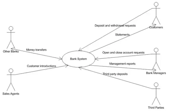
Names of your association are services. UseCase in center of diagram is context of services definition. See usecase diagram:

Vladimir
- 2,066
- 15
- 13
1
It could be done with a use case
http://en.wikipedia.org/wiki/Use_case
EDIT:
Reconsidering it, use case diagram should be the next step once the operations are defined so first you shouls make a system sequence diagram.
Aboca
- 575
- 2
- 9
-
But in use case diagram I need to split system to use cases right? I want to show context between actor and whole packed system. – user3565261 May 20 '14 at 13:50
-
I believe using use cases is the right way to do this, the depth you give it at the system layer is up to you. A use case diagram is supposed to provide guidance to convert business operations to enginering operations. That is if you want to use UML, which is in fact a modeling language for software engineering purposes, maybe you aren't actually looking for UML but a bussiness operations diagram – Aboca May 20 '14 at 13:59
-
Well, maybe you could try making a system squence diagram, could be what you are looking for, no need to make use cases that way: http://en.wikipedia.org/wiki/System_sequence_diagram – Aboca May 20 '14 at 14:07
1
If you're happy with going into the not complete superset of UML that is SysML, you can have proper Context diagrams there.
However, context diagrams in SysML are simply Block Diagrams showing system context… and Block Diagrams happen to be the same as UML2 Class diagram, where the classes are of stereotype «SysML::Block».
So you can define your context diagram in terms of aggregation of blocks to your system, with the relevant stereotypes, basing it on UML2 Class diagrams.
juandesant
- 703
- 8
- 16
0
I tend to use collaboration diagrams for this. So for each major scenario of each use case, draw a collaboration diagram showing the actors, with the application as a single entity in the middle, and messages travelling around that show how the application interacts with the actors in order to fulfil the scenario.
(I don't put too much detail in the messages -- I only want to show that there is a delegation of responsibility and some kind of interaction, but I don't care about details of actual messages, views, data etc.)
kevinrutherford
- 448
- 3
- 8
0
I find the context diagram does have a particular appeal. It sits well with business users, showing them the scope & parties of a system in a very easy way. So, I tend to create a context diagram, even in contexts where UML is prevalent.
JAL
- 41,701
- 23
- 172
- 300
Wim De Groote
- 1
- 1