1

I believe I am doing something fundamentally wrong when trying to import and test a transfer function in Simulink which was created within the System Identification Toolbox (SIT).

To give a simple example of what I am doing. I have an input which is an offset sinusoidal wave from 12 seconds to 25 seconds with an amplitude of 1 and a frequency of 1.5rad/s which gives a measured output.

I have used SIT to create a simple 2 pole 1 zero transfer function which gives the following agreement: SIT fit

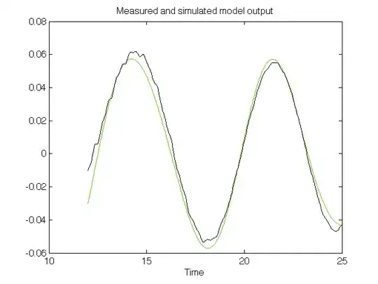
I have then tried to import this transfer function into Simulink for investigation in the following configuration which has a sinusoidal input of frequency 1.5rad/s and a starting t=12. The LTI system block refers to the transfer function variable within the workspace: Simulink schematic

When I run this simulation for 13 seconds the input to the block is as expected but the post transfer function signal shows little agreement with what would be expected and is an order of magnitude out.

pre: PRE signal

post: POST signal

Could someone give any insight into where I am going wrong and why the output from the tf in simulink shows little resemblance to the model output displayed in the SIT. I have a basic grasp of control theory but I am struggling to make sense of this.

Egon
  • 4,757
  • 1
  • 23
  • 38
Jimog
  • 35
  • 1
  • 4
  • These are the respective pre and post transfer function scopes: https://dl.dropboxusercontent.com/u/8037738/project/pre.PNG ; https://dl.dropboxusercontent.com/u/8037738/project/post.PNG – Jimog Feb 25 '14 at 14:36

1 Answers1

1

This could be due to different initial conditions used in SimuLink and the SI Toolbox, the latter should estimate initial conditions with the model, while Simulink does nothing special with initial conditions unless you specify them yourself.

To me it seems that your original signals are in periodic regime, since your output looks almost like a sine wave as well. In periodic regime, initial conditions have little effect. You can verify my assumption by simulating your model for a longer amount of time: if at the end, your signal reaches the right amplitude and phase lag as in your data, you will know that the initial conditions were wrong. In any case, you can get the estimated initial state from the toolbox, I think using the InitialState property of the resulting object.

Another thing that might go wrong, is the time discretization that you use in Simulink in case you estimated a continuous time model (one in the Laplace variable s, not in z or q).

edit: In that case I would recommend you check what Simulink uses to discretize your CT model, by using c2d in MATLAB and a setup like the one below in Simulink. In MATLAB you can also "simulate" the response to a CT model using lsim, where you have to specify a discretization method.

enter image description here

This set-up allows you to load in a CT model and a discretized variant (in this case a state-space representation). By comparing the signals, you can see whether the discretization method you use is the same one that SimuLink uses (this depends on the integration method you set in the settings).

Egon
  • 4,757
  • 1
  • 23
  • 38
  • Running the simulation for an extended period of time did not cause the output to reach the expected value or correlation. Though it appears that SIT's GUI uses `COMPARE` to predict some initial conditions when displaying the graph fits so you may be correct. I believe that to gather the initial conditions I have to covert the `tf` into a state space model and use `FINDSTATES` to gather estimated initial values. However, I calculate a new tf with explicit zero initial conditions but again this showed bad correlation in SIM. Would a fixed time step solver and continuous `tf` cause a problem? – Jimog Feb 25 '14 at 17:25
  • The solver you use can determine the result you have in a dominant way. I adapted my answer with a SL schematic to check discretization in Simulink. – Egon Feb 25 '14 at 18:44
  • You were correct that it was the initial conditions. To outline for anyone else with the same issue: 1)Convert tf to state-space model `sys_ss=ss(sys)` 2)Covert ss model into idss format `sys_idss=idss(sys_ss)` 3)compare model with data to find initial state `state=findstates(sys_idss,data)` 4)Use LTI block in Simulink with `sys_ss` and states gathered. Really thankful you highlighted that this was the issue Egon, much appreciated. – Jimog Feb 28 '14 at 11:23
  • Can you please tell if you used a discret or continuous solver? – user2536125 Mar 30 '15 at 15:49