0

In the LabView GUI I set the frequency to 300Hz = 1/300 seconds = 3.333 milliseconds and the pulse width to 2 milliseconds. This computes to a duty cycle of 60%.

enter image description here

Why are intervals between the pulses shown below not equal to 3.333 milliseconds? They look closer to 1 millisecond,which is way off.
enter image description here

Following is a wiring diagram I am using:
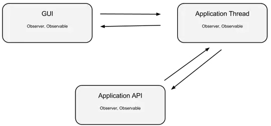
enter image description here

Is it possible the problem is my timed loop being set to loop every second? Should I loop faster? What kind of a loop should I be using?

user1068636
  • 1,871
  • 7
  • 33
  • 57
  • Could you show the configration of the Simulate Signal Express VI? – Ton Plomp Apr 03 '13 at 07:22
  • your first puls rise is at about 0.0002, the fall at about 0.0022 (so 2 ms width) and the second rise at about 0.0036, pretty much 3.3ms between the pulses – nos Apr 03 '13 at 11:10
  • Oh, I see. I was looking at the difference between a pulse drop and pulse rise. But I should have been looking at a the difference between pulse rise to pulse rise. Thanks guys. – user1068636 Apr 03 '13 at 17:45

1 Answers1

1

You have a pulse rise every 3.333 ms, so that's fine. You don't need a timed loop, the express VI will maintain phase, just make sure it runs more often than the amount of data the express VI produces. A simple wait ms will do.

Ton Plomp
  • 3,020
  • 1
  • 18
  • 35
  • How do I know how long for the wait ms to wait for? Is this something that can be determined? – user1068636 Apr 03 '13 at 23:30
  • It should be in the order of the created data by the express VI. The output waveform contains the number of samples and the sample frequency. – Ton Plomp Apr 04 '13 at 09:15