A few weeks ago, I removed the (dying) batteries from my Ultra 1000AP UPS to confirm their exact type before ordering new ones. I then got distracted by something, and forgot about the project for a while.
(For what it's worth, I've found posts on a Russian forum suggesting that it's a rebadged Powercom BNT-1000AP, and post on an Italian forum that seems to suggest that the Eurogroup Spikes-UP100 Pro has the same circuit board inside).
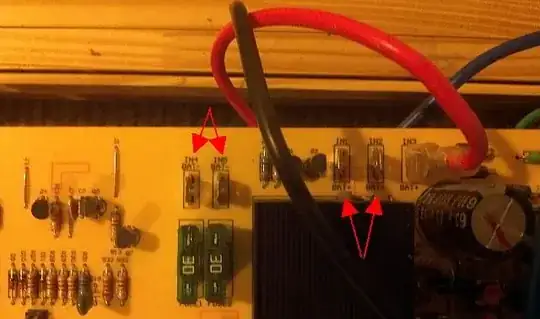
As luck would have it, I just discovered there are actually TWO adjacent terminals labeled BAT+ (IN1 & IN2), and two adjacent terminals labeled BAT- (IN4 & IN5). As far as I can tell, there's no hint printed anywhere indicating which two the battery wires are supposed to be connected to (or whether it matters). If somebody with this UPS could open it up and take a peek to see which ones the wires are connected to, I'd greatly appreciate it.
If it matters, JP1 (220/60hz) is open, and JP3 has 3&4 shorted, with 1&2 and 5&6 open. According to the legend on the board, that correlates to "120/240".
On a purely random note, if anybody has any idea what JP2 ("NL SD") does, I'd love to know.
Likewise, if anybody knows what MCU it uses, I'd also love to know.
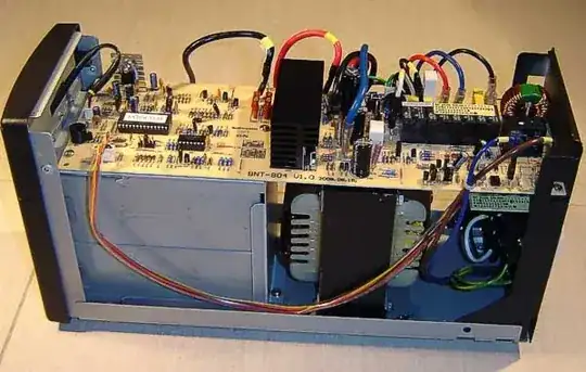
Here are the two pairs of contacts (note: the red and black wires you see are connected to the OUTPUT end. The battery's red and black leads were connected to one of each pair you see the arrows pointing to.
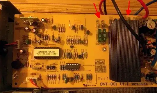
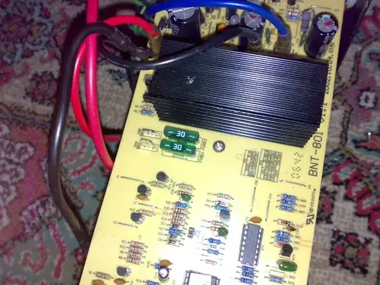
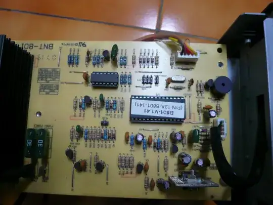
Here's a pic showing more of the board:
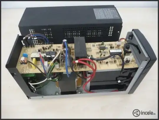
Stirring the pot a bit, here's a pic I finally managed to scrape up ( http://www.in4.pl/recenzje.htm?rec_id=610&rectr_str_numer=2 ) of a similar one, but I'm not ready to blindly assume it's the right pair of lugs for MY ups, because it's a slightly newer circuit board (804v1.0 instead of 801v1.1), and more importantly, it's a 220v Polish model instead of a 110v American one. I suspect that the circuit board itself hasn't changed much (in fact, the 804 board looks more or less identical to my 801 board), but I'm not prepared to rule out the possibility that 220v configurations might have the battery leads connected to a different pair of lugs. I really need to either find a pic of a US/Canadian/Mexican model, or find a circuit diagram for the BNT-1000AP (with BNT-801 circuit board) that conclusively identifies why there are 4 lugs for two battery wires.
Here's one I found in a Turkish forum ( http://forum.donanimhaber.com/m_11377295/mpage_2/key_/tm.htm ) that has the exact same board as mine (BNT-801v1.1), but I have no idea WTF is going on with the battery leads in the pic. I think he actually had both leads disconnected, and the black lead just happened to be randomly grazing the general vicinity of a "+" terminal. Either way, it's another 220v configuration, so it's still non-authoritative absent a diagram to the contrary.
Just to keep things lively, I found more pics of a BNT-1000AP on another Turkish site ( http://www.incele.info/index.php?option=com_content&view=article&catid=34:incelemeler&id=130:powercom-ups&Itemid=77 ) , except this one shows the red lead connected to IN3, and the black lead connected to IN5. Wait a sec... IN3 ?!? Oh dear...
Here's another one, in traditional Chinese, jumpered for 115/230v, using IN2 and IN5 ( http://ups--bnt-1000ap.blogspot.com/2010/11/ups-bnt-1000ap.html ):

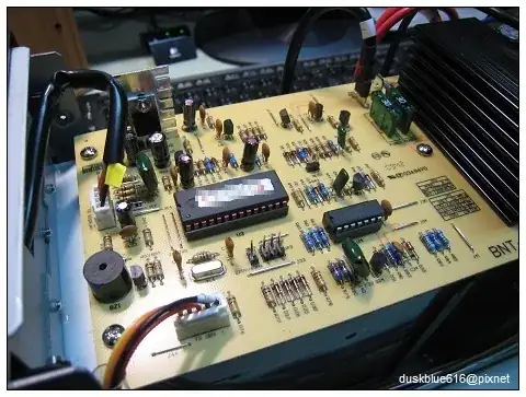
Another Chinese site with pics ( http://duskblue616.pixnet.net/blog/post/25824076-%5B%E5%91%A8%E9%82%8A%5D%E7%A7%91%E9%A2%A8%E9%BB%91%E6%AD%A6%E5%A3%ABbnt1000ap )... negative on IN4, can't see what red is connected to.
Score so far:
Polish 1200UA, 115/230v, BNT-801v1.1 (2002.10.04) = IN2+, IN4-
Turkish 1000UA, 110/220v, BNT-801v1.1 (2002.??.??) = unknown
Turkish 1000UA, 110/220v, BNT-80????? = IN3+ (WTF?!?), IN5-.
Chinese 1000UA, 115/230v, BNT-801v???? = IN2+, IN5-
Chinese 1000UA, 115/230v, BNT-801v1.1 = (unknown red), IN4-.
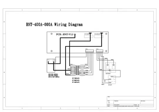
I really want to find a circuit diagram for the BNT-1000AP like the one posted for the 600AP. There appear to have been a bunch hosted at megaupload, but they're all gone now :(