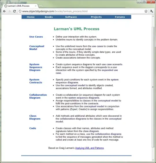
In IT projects we create so-call project diagrams based on UML diagrams. In the majority of projects using UML diagrams (Choi, H., Yeom, K.: An Approach to Software Architecture Evaluation with the 4+1 View Model of Architecture. In: Ninth Asia-Pacific Software Engineering Conference, pp. 286—293. IEEE Computer Society, 2002), (Kennaley M.: The 3+1 Views of Architecture (in 3D): An Amplification of the 4+1 View-point Framework. In Seventh Working IEEE/IFIP Conference, pp. 299—302. IEEE Com-puter Society, 2008), use case diagrams are developed at the beginning of software development to describe the main functions of the software-based system. Then class diagrams are created to show the structure of the system, and state machine diagrams are built to show the behaviour of system’s elements (Issa A., Abu Rub F.A.: Performing Early Feasibility Studies of Software Development Projects Using Business Process Models, Proceedings of the World Congress on Engineer-ing 2007 Vol I WCE 2007, July 2 - 4, 2007, London, U.K.), (Dijkman R.M., Joosten S.M.: An Algorithm to Derive Use Case Diagrams from Business Process Models, 6th International Conference on Software Engineering and Applications (SEA), Anaheim, CA, USA, Acta Press, pp. 679-684, 2002). Subsequently activity or sequence diagram can be used in order to verify consistency of other diagrams. These diagrams are also using visualizing scenarios i.e. – use case realization diagrams.
But in my UML projects first I create context diagram based on activity UML diagram. Context diagram contains one main process, a few events on input, and a few products or services on output.
Then I create decomposition diagram, which next enable to build busioness use case diagram.
Now, for each use case, I first prepare use case realisation diagram based on activity diagram.
From each use case realisation diagram I derive: class, state, and system uses case diagrams.
Next I may create a sequence diagram based on the system use case diagram to show intrnal behaviour and structure of IT system. In the end I create component diagram (based on the sequence diagram), and deployment diagram (based on the component diagram).
Stanisław Jerzy Niepostyn, project-media.pl